现在板子已经到手,听说要更新controlsuit到 v1.1,然后更新了以后发现ccs6.0的编译器不行,要更新到v6.4,那么问题来了。
第一:我用controlsuit到 v1.0里面的例程能实现吗?
第二:由于购买这个板子时候只有.out文件,我就按照快速启动接线什么的确定无误,想实现点亮板上50w的灯泡。
然后我就按新建一个ccxml文件——luanch selection configuration——最后就把购买板子时候的.out文件load进去,(28035芯片是用大的jtag口load,led1常亮led3闪烁;然后28027的用小usb口load,led1常亮led2闪烁,我是这样做的不知道对不对?),结果只有load进去的ccs debug画面只有4个键是能用的(图1、2、3、4),并没有run这个功能,
我的问题是:怎么才能点亮50w灯泡?

jiabin huang:
回复 Eric Ma:
你好,这个控制卡上面没有usb jtag口。问题是:
1:那这个控制卡的程序是怎样烧写进去的,如果控制卡里有程序的话我在运行板的时候为什么没有反应?如果没有程序的话,那又不提供我自己烧进去的接口,这个控制卡不就没有用了吗?
2:控制卡的程序不是从M7模块的jtag口(第二个图右下角)烧进去的吗?还是从M5模块的mini-USB烧进去?
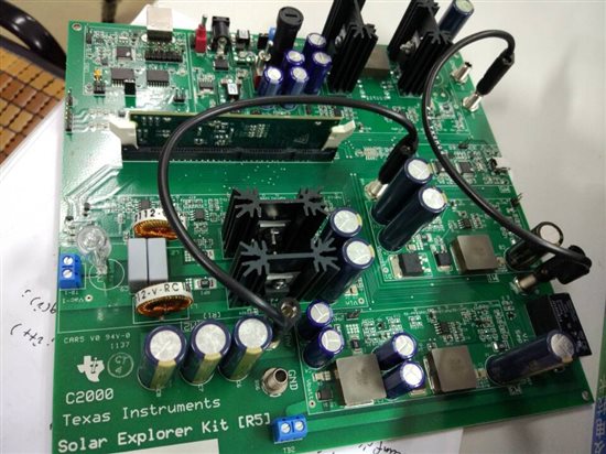
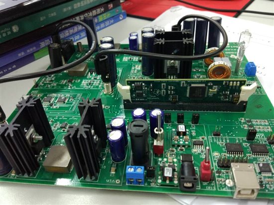
现在板子已经到手,听说要更新controlsuit到 v1.1,然后更新了以后发现ccs6.0的编译器不行,要更新到v6.4,那么问题来了。
第一:我用controlsuit到 v1.0里面的例程能实现吗?
第二:由于购买这个板子时候只有.out文件,我就按照快速启动接线什么的确定无误,想实现点亮板上50w的灯泡。
然后我就按新建一个ccxml文件——luanch selection configuration——最后就把购买板子时候的.out文件load进去,(28035芯片是用大的jtag口load,led1常亮led3闪烁;然后28027的用小usb口load,led1常亮led2闪烁,我是这样做的不知道对不对?),结果只有load进去的ccs debug画面只有4个键是能用的(图1、2、3、4),并没有run这个功能,
我的问题是:怎么才能点亮50w灯泡?

jiabin huang:
回复 Eric Ma:
你好,还有2个问题就是:
1:控制卡有很多种吗?买的时候好像没有这个提醒啊,但是现在控制卡原理上是存在这个jtag口,为什么买回来就没有了呢?图如下
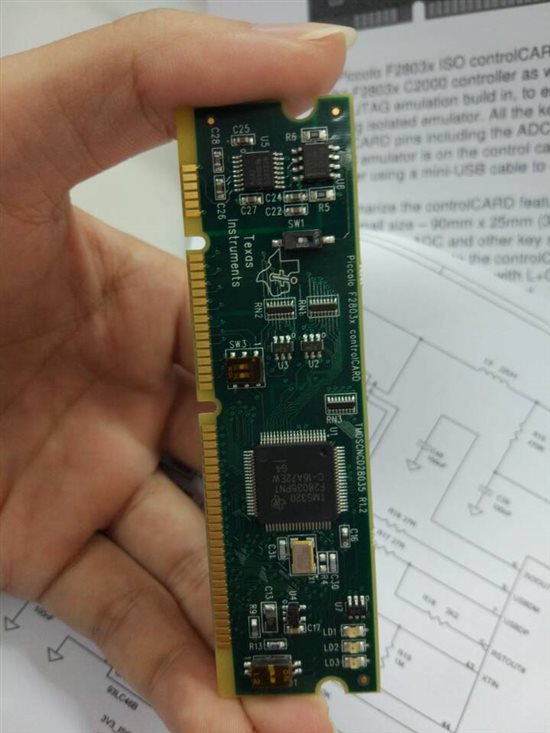
2:上边 部分的sw1是作用是什么?
希望得到帮助,谢谢
现在板子已经到手,听说要更新controlsuit到 v1.1,然后更新了以后发现ccs6.0的编译器不行,要更新到v6.4,那么问题来了。
第一:我用controlsuit到 v1.0里面的例程能实现吗?
第二:由于购买这个板子时候只有.out文件,我就按照快速启动接线什么的确定无误,想实现点亮板上50w的灯泡。
然后我就按新建一个ccxml文件——luanch selection configuration——最后就把购买板子时候的.out文件load进去,(28035芯片是用大的jtag口load,led1常亮led3闪烁;然后28027的用小usb口load,led1常亮led2闪烁,我是这样做的不知道对不对?),结果只有load进去的ccs debug画面只有4个键是能用的(图1、2、3、4),并没有run这个功能,
我的问题是:怎么才能点亮50w灯泡?

jiabin huang:
回复 Eric Ma:
我用万用表测了板子都是有电的,最后我才发现了一个问题,就是我M7的JTAG口没有链接到F28035控制卡,所以烧不进去程序,我使用排除法:
1:我把F28035控制卡取出来和不取出来放在板上进行test connection出现的错误都是一样的。请问如何解决?
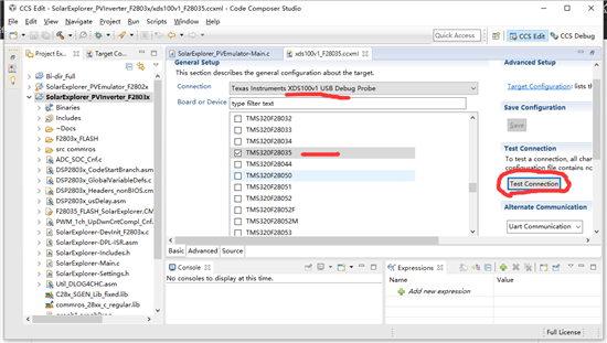
[Start: Texas Instruments XDS100v1 USB Debug Probe_0]
Execute the command:
%ccs_base%/common/uscif/dbgjtag -f %boarddatafile% -rv -o -F inform,logfile=yes -S pathlength -S integrity
[Result]
—–[Print the board config pathname(s)]————————————
C:\Users\MR2790~1.WHI\AppData\Local\TEXASI~1\ CCS\ccs6.1\0\0\BrdDat\testBoard.dat
—–[Print the reset-command software log-file]—————————–
This utility has selected a 100- or 510-class product.This utility will load the adapter 'jioserdesusb.dll'.The library build date was 'Feb 18 2015'.The library build time was '23:56:50'.The library package version is '5.1.641.0'.The library component version is '35.34.40.0'.The controller does not use a programmable FPGA.The controller has a version number of '4' (0x00000004).The controller has an insertion length of '0' (0x00000000).This utility will attempt to reset the controller.This utility has successfully reset the controller.
—–[Print the reset-command hardware log-file]—————————–
The scan-path will be reset by toggling the JTAG TRST signal.The controller is the FTDI FT2232 with USB interface.The link from controller to target is direct (without cable).The software is configured for FTDI FT2232 features.The controller cannot monitor the value on the EMU[0] pin.The controller cannot monitor the value on the EMU[1] pin.The controller cannot control the timing on output pins.The controller cannot control the timing on input pins.The scan-path link-delay has been set to exactly '0' (0x0000).
An error occurred while hard opening the controller.
—–[An error has occurred and this utility has aborted]——————–
This error is generated by TI's USCIF driver or utilities.
The value is '-150' (0xffffff6a).The title is 'SC_ERR_FTDI_FAIL'.
The explanation is:One of the FTDI driver functions used duringconfiguration returned a invalid status or an error.
[End: Texas Instruments XDS100v1 USB Debug Probe_0]
2:板子的信息如下:
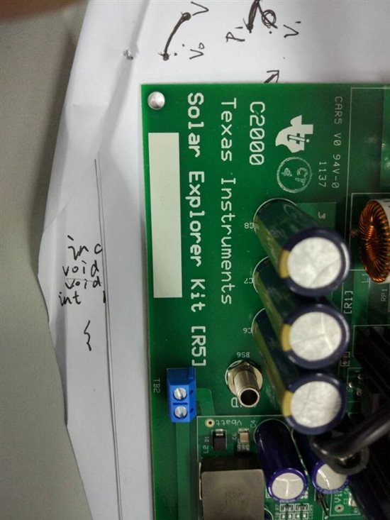
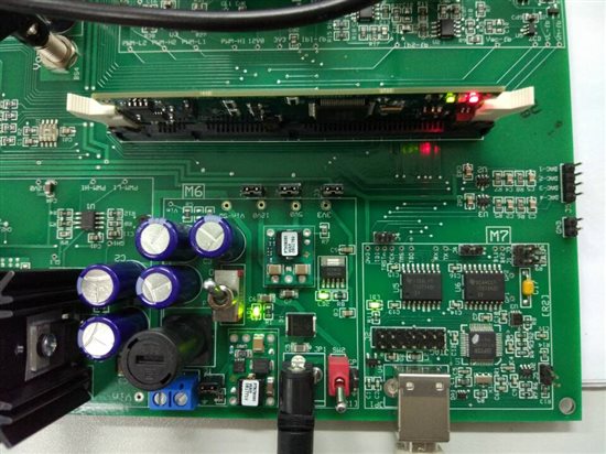
现在板子已经到手,听说要更新controlsuit到 v1.1,然后更新了以后发现ccs6.0的编译器不行,要更新到v6.4,那么问题来了。
第一:我用controlsuit到 v1.0里面的例程能实现吗?
第二:由于购买这个板子时候只有.out文件,我就按照快速启动接线什么的确定无误,想实现点亮板上50w的灯泡。
然后我就按新建一个ccxml文件——luanch selection configuration——最后就把购买板子时候的.out文件load进去,(28035芯片是用大的jtag口load,led1常亮led3闪烁;然后28027的用小usb口load,led1常亮led2闪烁,我是这样做的不知道对不对?),结果只有load进去的ccs debug画面只有4个键是能用的(图1、2、3、4),并没有run这个功能,
我的问题是:怎么才能点亮50w灯泡?

Eric Ma:
回复 jiabin huang:
控制卡有两种,一种是卡上自带隔离仿真器,另外一种就是你那种,只有最小系统,具体差别,见各自原理图。
C:\ti\controlSUITE\development_kits\~controlCARDs\CC2803xISOHWdevPkg
C:\ti\controlSUITE\development_kits\~controlCARDs\CC2803xHWdevPkg_v2_0
你要好好看一下我给你的那个路径下面的相关文档,里面会高速你如何配置相关的开关,烧写程序和调试。不要没看过原理图和说明手册就上电,否则一不小心就炸机,那就不好了。
你这个板子的隔离仿真器是最后一张图中的M7。
ERIC
 TI中文支持网


