文件目录(C:\ti\controlSUITE\development_kits\TMDSIDDK_v2.0\IDDK_PM_Servo_F2837x_v2_00_00_00)
目录下的IDDK_PM_Servo_F2837x.C文件中:
母线电压配置:
// Bus Voltage Feedback at B0 (not used) 母线电压反馈
// **************************************
AdcbRegs.ADCSOC3CTL.bit.CHSEL = 0; // SOC3 will convert pin B0
AdcbRegs.ADCSOC3CTL.bit.ACQPS = 30; // sample window in SYSCLK cycles
AdcbRegs.ADCSOC3CTL.bit.TRIGSEL = 5; // trigger on ePWM1 SOCA/C
AdcbRegs.ADCPPB4CONFIG.bit.CONFIG = 3; //dx PPB is associated with SOC3
AdcbRegs.ADCPPB4OFFCAL.bit.OFFCAL = 0; //dx Write zero to this for now till offset ISR is run


hang1:
建议 不加采样信号或 直接采样内部进准电压进行测试对比。
文件目录(C:\ti\controlSUITE\development_kits\TMDSIDDK_v2.0\IDDK_PM_Servo_F2837x_v2_00_00_00)
目录下的IDDK_PM_Servo_F2837x.C文件中:
母线电压配置:
// Bus Voltage Feedback at B0 (not used) 母线电压反馈
// **************************************
AdcbRegs.ADCSOC3CTL.bit.CHSEL = 0; // SOC3 will convert pin B0
AdcbRegs.ADCSOC3CTL.bit.ACQPS = 30; // sample window in SYSCLK cycles
AdcbRegs.ADCSOC3CTL.bit.TRIGSEL = 5; // trigger on ePWM1 SOCA/C
AdcbRegs.ADCPPB4CONFIG.bit.CONFIG = 3; //dx PPB is associated with SOC3
AdcbRegs.ADCPPB4OFFCAL.bit.OFFCAL = 0; //dx Write zero to this for now till offset ISR is run


dxss dx:
回复 hang1:
你好!很感谢你的回复!
我进行A0 、A1、B0 、B1、D0 、D1等管脚进行对比:
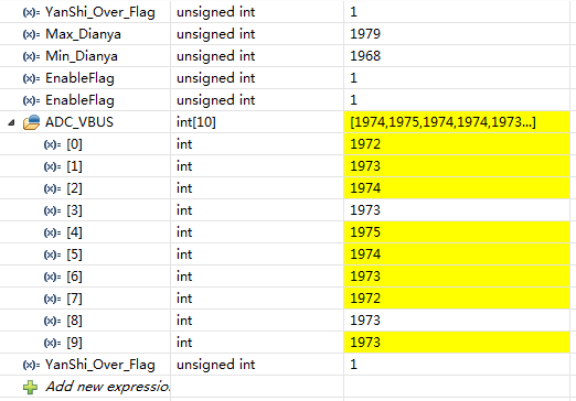
1、我将以上连接电阻断开,不采电压,进行F28377D和F28379D 进行对比,发现采集数据都是0;
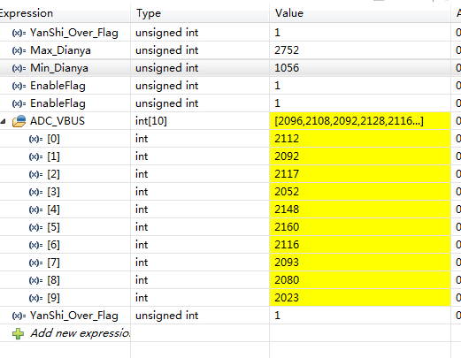
2、当我仅仅在端口接相同的电压值时,就会发现F28377D,采样正确。而F28379D,采样跳动太大,如上图所示。
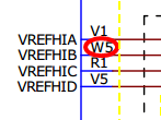
3、对两个芯片的开发板的,都进行ADC参考电压测量 ,使用示波器和万用表,发现参考电压都是3V .
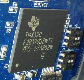
以上是实验现象;是否因为F28379D(型号: )是实验芯片,而存在问题的?
麻烦帮忙解决!多谢!
 TI中文支持网


