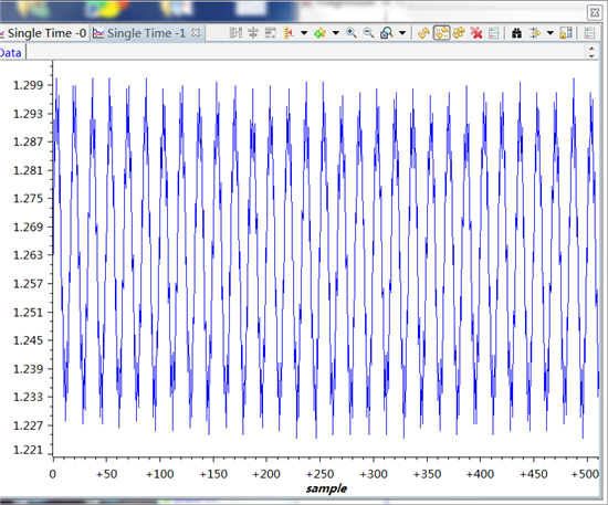
例程如下:
#include "DSP2833x_Device.h" // DSP2833x Headerfile Include File
#include "DSP2833x_Examples.h" // DSP2833x Examples Include File
// Prototype statements for functions found within this file.
interrupt void adc_isr(void);
// Global variables used in this example:
Uint16 LoopCount;
Uint16 ConversionCount;
Uint16 Voltage1[10];
main()
{
// Step 1. Initialize System Control:
// PLL, WatchDog, enable Peripheral Clocks
// This example function is found in the DSP2833x_SysCtrl.c file.
InitSysCtrl();
EALLOW;
#if (CPU_FRQ_150MHZ) // Default – 150 MHz SYSCLKOUT
#define ADC_MODCLK 0x3 // HSPCLK = SYSCLKOUT/2*ADC_MODCLK2 = 150/(2*3) = 25.0 MHz
#endif
#if (CPU_FRQ_100MHZ)
#define ADC_MODCLK 0x2 // HSPCLK = SYSCLKOUT/2*ADC_MODCLK2 = 100/(2*2) = 25.0 MHz
#endif
EDIS;
// Step 2. Initialize GPIO:
// This example function is found in the DSP2833x_Gpio.c file and
// illustrates how to set the GPIO to it's default state.
// InitGpio(); // Skipped for this example
// Step 3. Clear all interrupts and initialize PIE vector table:
// Disable CPU interrupts
DINT;
// Initialize the PIE control registers to their default state.
// The default state is all PIE interrupts disabled and flags
// are cleared.
// This function is found in the DSP2833x_PieCtrl.c file.
InitPieCtrl();
// Disable CPU interrupts and clear all CPU interrupt flags:
IER = 0x0000;
IFR = 0x0000;
// Initialize the PIE vector table with pointers to the shell Interrupt
// Service Routines (ISR).
// This will populate the entire table, even if the interrupt
// is not used in this example. This is useful for debug purposes.
// The shell ISR routines are found in DSP2833x_DefaultIsr.c.
// This function is found in DSP2833x_PieVect.c.
InitPieVectTable();
// Interrupts that are used in this example are re-mapped to
// ISR functions found within this file.
EALLOW; // This is needed to write to EALLOW protected register
PieVectTable.ADCINT = &adc_isr;
EDIS; // This is needed to disable write to EALLOW protected registers
// Step 4. Initialize all the Device Peripherals:
// This function is found in DSP2833x_InitPeripherals.c
// InitPeripherals(); // Not required for this example
InitAdc(); // For this example, init the ADC
// Step 5. User specific code, enable interrupts:
// Enable ADCINT in PIE
PieCtrlRegs.PIEIER1.bit.INTx6 = 1;
IER |= M_INT1; // Enable CPU Interrupt 1
EINT; // Enable Global interrupt INTM
ERTM; // Enable Global realtime interrupt DBGM
LoopCount = 0;
ConversionCount = 0;
// Configure ADC
AdcRegs.ADCMAXCONV.all = 0x0000; // Setup 1 conv's on SEQ1
AdcRegs.ADCCHSELSEQ1.bit.CONV00 = 0x0; // Setup ADCINA0 as 1st SEQ1 conv.
AdcRegs.ADCTRL2.bit.EPWM_SOCA_SEQ1 = 1;// Enable SOCA from ePWM to start SEQ1
AdcRegs.ADCTRL2.bit.INT_ENA_SEQ1 = 1; // Enable SEQ1 interrupt (every EOS)
// Assumes ePWM1 clock is already enabled in InitSysCtrl();
EPwm1Regs.ETSEL.bit.SOCAEN = 1; // Enable SOC on A group
EPwm1Regs.ETSEL.bit.SOCASEL = 4; // Select SOC from from CPMA on upcount
EPwm1Regs.ETPS.bit.SOCAPRD = 1; // Generate pulse on 1st event
EPwm1Regs.CMPA.half.CMPA = 0x0080; // Set compare A value
EPwm1Regs.TBPRD = 0xffff; // Set period for ePWM1
EPwm1Regs.TBCTL.bit.CTRMODE = 0; // count up and start
// Wait for ADC interrupt
for(;;)
{
LoopCount++;
}
}
interrupt void adc_isr(void)
{
Voltage1[ConversionCount] = AdcRegs.ADCRESULT0 >>4;
// If 40 conversions have been logged, start over
if(ConversionCount == 9)
{
ConversionCount = 0;
}
else ConversionCount++;
// Reinitialize for next ADC sequence
AdcRegs.ADCTRL2.bit.RST_SEQ1 = 1; // Reset SEQ1
AdcRegs.ADCST.bit.INT_SEQ1_CLR = 1; // Clear INT SEQ1 bit
PieCtrlRegs.PIEACK.all = PIEACK_GROUP1; // Acknowledge interrupt to PIE
return;
}
用a0通道采样1.1v的电压,正确的Voltage1[ConversionCount] 的值应该是1500左右,但是采样出来的Voltage1[ConversionCount] 的值一直是170多,不知上面// Configure ADC
AdcRegs.ADCMAXCONV.all = 0x0000; // Setup 1 conv's on SEQ1
AdcRegs.ADCCHSELSEQ1.bit.CONV00 = 0x0; // Setup ADCINA0 as 1st SEQ1 conv.
AdcRegs.ADCTRL2.bit.EPWM_SOCA_SEQ1 = 1;// Enable SOCA from ePWM to start SEQ1
AdcRegs.ADCTRL2.bit.INT_ENA_SEQ1 = 1; // Enable SEQ1 interrupt (every EOS)
// Assumes ePWM1 clock is already enabled in InitSysCtrl();
EPwm1Regs.ETSEL.bit.SOCAEN = 1; // Enable SOC on A group
EPwm1Regs.ETSEL.bit.SOCASEL = 4; // Select SOC from from CPMA on upcount
EPwm1Regs.ETPS.bit.SOCAPRD = 1; // Generate pulse on 1st event
EPwm1Regs.CMPA.half.CMPA = 0x0080; // Set compare A value
EPwm1Regs.TBPRD = 0xffff; // Set period for ePWM1
EPwm1Regs.TBCTL.bit.CTRMODE = 0; // count up and start
有啥错误,还请指导下,谢谢
mangui zhang:
请参考相关帖子
http://www.deyisupport.com/question_answer/microcontrollers/c2000/f/56/t/86364.aspx
 TI中文支持网


